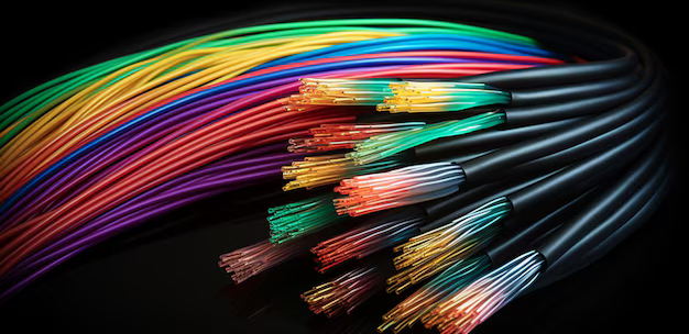
An introduction to telephone cables
Summary of IEC 60189-2
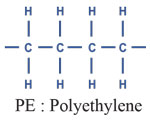
Low frequency cables and wires with PVC insulation and PVC coating
Part 2: Cables in pairs, threes, fours and fives for internal installation
Range :
This part of IEC 60189 applies to indoor installation cables intended to connect:
– transmission equipment;
– Telecommunication equipment;
– Equipment for data processing
1) Conductor
Conductive material
The conductor must be made of annealed copper, of uniform quality and free from defects.
Copper properties should be in accordance with IEC 60028 standard.
Conductor type
The conductor must consist of a single strand that is circular in cross-section.
end of the conductor
The conductor may be plain or tinned.
Conductor dimensions
The conductor is determined by its nominal diameter. The nominal diameter is 0.4, 0.5, 0.6, 0.8 mm.
Continuity of the conductor
Usually the conductor should be drawn in one piece.
If necessary, joints in the conductor are permitted, provided that the breaking strength of a joint is not less than 85% of the breaking strength of the non-permitted conductor.
2) Insulation
-Insulating materials
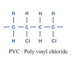
The insulation should consist of polyvinyl chloride (PVC).
Insulation thickness
The insulation shall be continuous with as uniform a thickness as possible, minimum 0.15 mm for nominal conductor diameter up to 0.6 mm and minimum 0.25 mm for nominal conductor diameter 0.8 mm.

3) Cabling element
A cabling element must be
– A pair of two insulated conductors that are twisted together and wire a and wire b are marked
4) Packaging
The cable core may be wrapped with a protective layer of non-wicking, non-wicking material (for example, a helical or longitudinal covering of one or more overlapping strips or a continuous thin sheath).
If a screen is provided, the protective layer should be mandatory.
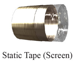
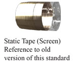
5) Screening
The cable core may have a screen. It must consist of copper or aluminum strip with a minimum thickness of 0.04 mm or thin strip of the same material with a minimum thickness of 0.008 mm.
Laminated to a plastic strip.
The tape shall be spirally wound or applied longitudinally around the wrapped core with an overlap of at least 20% or 6 mm, whichever is less.
One or more tinned copper wires must be placed in continuous contact with the surface of the metal strip in the cable.
The wires may be of circular or flat cross-section: the total cross-sectional area shall not be less than 0.125 mm2.
The panel may be provided with an outer protective layer of non-wicking, non-wicking material (eg, a longitudinal or spiral wrap of one or more overlapping strips).
6) Sheath
-Sheath material
The sheath should be made of polyvinyl chloride.
-Sheath color
The color of the sheath is preferably gray
Summary of IEC 60708
Low frequency cables with polyolefin insulation and moisture barrier polyolefin sheath
Range
This standard is intended to define polyolefin insulated cables for installation in outdoor local area networks.
This standard applies to polyolefin insulated and moisture barrier telephone cables, filled or unfilled with copper conductors, and used as:
a) Cables suitable for installation in channels.
b) Cables suitable for direct burial in the ground.
c) Cables with integrated suspension strands for aerial installations.
This standard is in accordance with ITU-T recommendations.
This standard includes general design details and requirements for dimensions and other construction details as well as mechanical, electrical and environmental characteristics for all types of low frequency cables with polyolefin insulation (solid or cellular), filled or unfilled, and moisture barrier polyolefin sheath. be with integrated suspension string).
Conductive material
The conductor must be made of annealed copper, of uniform quality and free from defects.
Copper properties should be in accordance with IEC 60028 standard.
Conductor type
The conductor must consist of a single strand that is circular in cross-section.
End of the conductor
The conductor should be simple.
Conductor dimensions
The conductor is determined by its nominal diameter. The nominal diameter is 0.4, 0.5, 0.6, 0.8 mm.
The nominal diameter should be at least 0.4 mm.
Continuity of the conductor
Joints in the conductor are allowed provided that the tensile strength of a joint is not less than 90% of the tensile strength of the unjointed conductor.
2) Insulation
-Insulating materials
The conductor shall be covered with solid or cellular polyolefin insulation or any combination thereof. – (polyethylene or polypropylene)
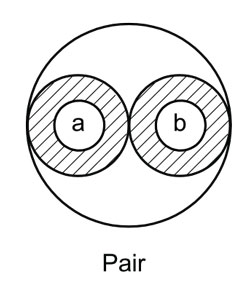
3) Cabling element
A cabling element must be
– A pair of two insulated conductors that are twisted together and wire a and wire b are marked
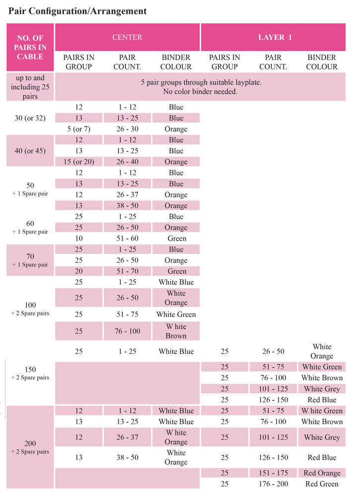
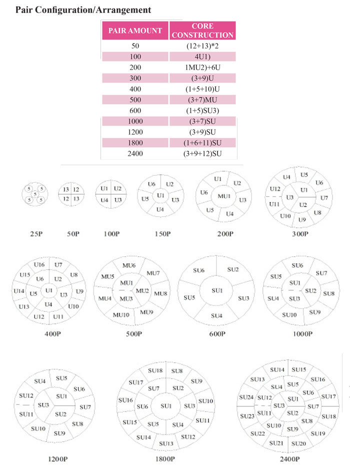
4) Threading
The cable elements must be converted into a number of sub-units or units that can be serially cut to produce the required number of pairs.
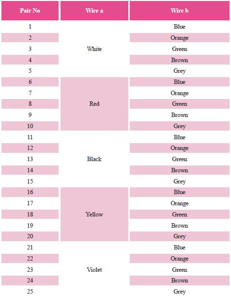
– 25 pairs
Pairs shall be identified by each insulated conductor having a color in accordance with the color scheme provided in Annex C. Each group of subunits that make up the number of 25 pairs must be marked with a common color of connections.
5) Filling
For filled cables, the cable core gaps must be continuously filled with a suitable compound to prevent water penetration into the cable.
6) Core protection
The cable core may have a protective layer (for example, a spiral or longitudinal covering of one or more strips).
7) Sheath
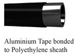
– General: The structure of aluminum multi-layer polyethylene sheath is specified for both underground cables and aerial cables. This type of sheath also offers screening.
For aerial cables, figure “8” structure is specified.
Circular sheath cables can also be used as aerial cables.
– Sheath material: aluminum tape is glued to the polyethylene sheath.
– Aluminum tape: Aluminum tape must be covered with a polymer film on at least one side. Aluminum strip without polymer layer should have a nominal thickness of at least 0.15 mm.
– Polyethylene: Polyethylene must have at least 2.0% carbon black.
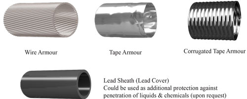
8) Cable protection
As recommended by ITT L.3, armor can be applied to the sheath to improve the cable’s strength against mechanical damage, rodent and insect attack, and/or to improve screening efficiency against electromagnetic interference and lightning discharges. Armor may be made by metal tape (or tape) or wire with a protective layer.
Summary of IEC 60708 (Electrical requirements)
Low frequency cables with polyolefin insulation and
Moisture barrier polyolefin sheath
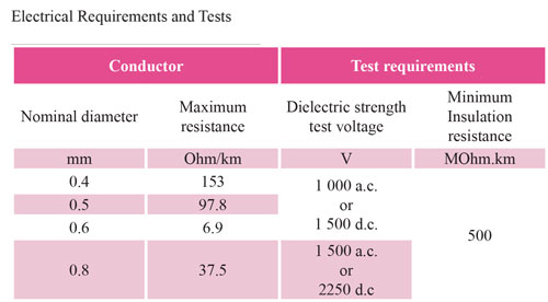
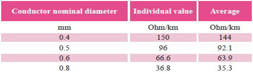
1) Electrical resistance of the conductor
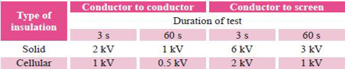
2) dielectric strength
The dielectric strength of the insulation should be checked on the finished cable.
The insulation must withstand the application of d.c. Test voltage
Test voltages for alternate durations are given in the table below.
3) insulation resistance
Insulation resistance at 20 degrees Celsius should not be less than:
– For cables filled with 1 500 MOhm x km
– or unfilled cables 5000 MOhm x km
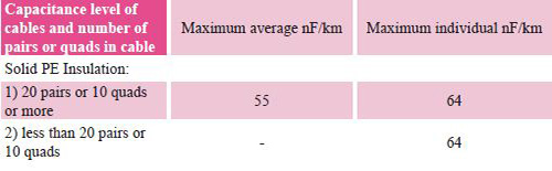
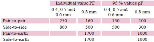
4) Mutual capacity
The mutual capacitance should not exceed the values given in the table below.
5) Capacity imbalance
The capacitance imbalance should not exceed the values given in the following table for every 500 meters of cable length:
*** The following parameters are not applicable for A-2Y(St)2Y cables with static plate.
6) weakening
The attenuation values depend on the cable design and should be provided by the manufacturer.
Measurement method based on IEC 61156-1, 3.3.2.
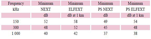
7) Near End Crosstalk (next)
NEXT values are given in Table 6.
Measurement method according to IEC 61156-1, 3.3.3.
8) ELFEXT
ELFEXT values are given in the table below.
Measurement method based on IEC 61156-1, 3.3.5.
9) Power sum (PS) interference loss
The values of the total power losses of the near-end junction and the equal level at the end are given in the table below.
Measurement method according to IEC 61156-1
10) characteristic impedance
The nominal value of the characteristic impedance Z0 of the cable must be in the range of 80 ohms
130 ohms at 1 MHz, depending on design. Maximum deviation from the nominal characteristic
Impedance should be within ± 15%.
Measurement method based on IEC 61156-1, 3.3.6.
11) Release speed
The propagation speed should be more than 60% at 1 MHz.
Measurement method according to IEC 61156-1, 3.3.1.
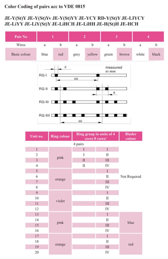
Pair color coding according to IEC 60708, 60189 A-2Y
4) Threading
Cable elements must be converted into a number of sub-units or units that can be serially cut to produce the required number of cores, pairs or quads.
Other technical information
Do you need advice?