Summary of IEC 60092-376 (2003)
Electrical installations on ships – Part 376: Cables for control and instrumentation circuits 150/250 V (300 V)
Scope and topic:
This part of IEC 60092 applies to screened and unscreened cables of control and instrumentation circuits on ships and offshore units.
The cables have extruded solid insulation with a voltage rating of 150/250 V (300 V) and are intended for fixed installations.
Calculated voltage:
The standard nominal voltage Uo/U (Um) is as follows:
Uo/U (Um) = 150 V/250 V (300 V) a.c.
in determining the voltage of the cables;
Uo: the rated power frequency voltage between the conductor and the ground or the metal cover for which the cable is designed.
U: voltage frequency is the rated power between the conductors for which the cable is designed.
Um: The maximum value is the highest system voltage that the equipment may be used for.
DC voltage up to 1.5 times a.c. Voltage can be used, provided the voltage to ground does not exceed 250V.
1) Conductors:
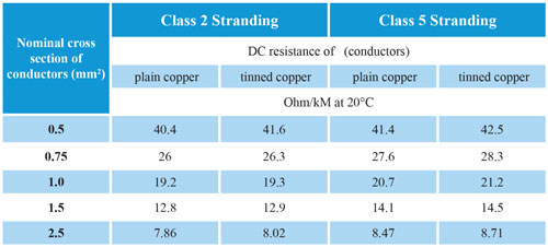
The material, metal covering, insulation, class and form of the conductors shall conform to IEC 60092-350 and shall be Class 2 or Class 5 circular structures with a cross-sectional area of 0.50 mm2, 0.75 mm2, 1.0 mm2, 1.5 mm2 or 2.5 mm2.
Note: The preferred conductor size is 0.75mm2 and 1.5mm2.
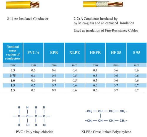
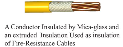
2) Insulation system:
The insulation system must include one of the following:
2-1) One of the insulating compounds shown in the table below
2-2) A combination of one or more layers of mineral tape(s) and a layer of one of the insulating compounds shown in the table below (example: mica glass tape + XLPE)
3) Cabling
3-1) core assembly (multi-core cables)
Individual cores must be wrapped in concentric layers.
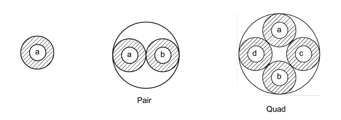
2-3) Formation of double, triple or quadruple units.
Nuclei must be twisted with a left or right hand to form a double, triple or quadruple unit.
The lamination length of screened cores individually or collectively shall not exceed 120 mm for sizes below 1.5 mm2 and 150 mm for sizes 1.5 mm2 and above.
3-4) Number of cores
It is recommended that the number of cores be selected from one of the following: 2, 4, 7, 12, 19, 27, 37.
5-3) the number of double, triple or quadruple units
It is recommended to choose the number of paired units from one of the following: 1, 3, 7, 12, 19, 27, 37.
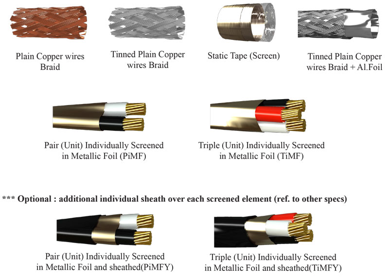
4) Electrostatic screen
1-4) Double, triple or quadruple structures are glued separately
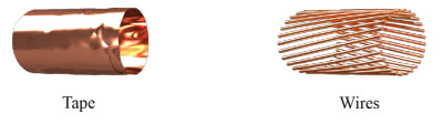
When a pair of separate strip plates, triple or quadruple construction is required, each pair, triple or quadruple shall have a multilayer electrostatic screening strip applied with the metal side in electrical contact with the discharge wire. The nominal overlap should not be less than 25%.
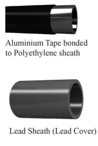
Multi-layer electrostatic screening tape must be either bonded to polyester with a minimum aluminum thickness of 0.008 mm and a minimum polyester thickness of 0.010 mm, or copper bonded to polyester with a minimum copper thickness of 0.018 mm and a minimum thickness of polyester. Polyester 0.023 mm.
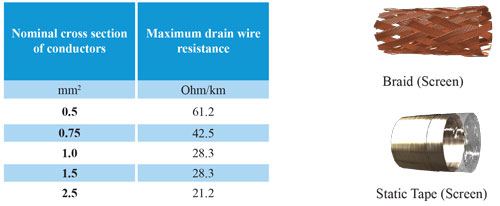
The discharge wire shall consist of a number of strands of tinned copper wire in the case of aluminum laminated tape and plain annealed or tinned copper wires in the case of copper laminated tape. The discharge wire must have a maximum resistance according to the table below
2-4) individually woven pair, triple or
quadruple constructions
When a separate braided pair, triple or quadruple construction is required, each pair, triple or quadruple shall have a non-hygroscopic separating strip applied to the cores and under the braid.
The nominal overlap should not be less than 25%.
The braid should be plain copper wire or with metal coating. The minimum diameter of the braid wire shall: If necessary, to aid in termination, a drain wire may be applied below and in direct contact with the braid plate. The discharge wire should consist of a number of tinned or plain annealed copper strands. Wires. The discharge wire must have a maximum resistance according to the table below.
4-3) collective screened structures
Similar to 4-1) and 4-2); Banded and woven screen types are allowed.
5) Metal woven armor
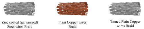
In this standard, braided wires are:
Zinc coated steel (galvanized) or
copper (plain or tinned),
Note: In the case of plain or tinned copper wire braids, these may also provide the function of an electrostatic.
Collective screens provided they are terminated to ground.
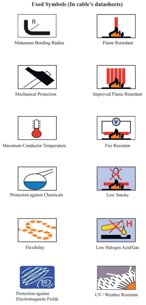
6) Pod(s)
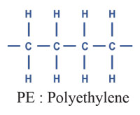
It can be one of the following materials; Without PVC, polyethylene, halogen.
The sheath must be black or gray unless otherwise specified.
Note: The sheath may have other colors, so it creates a visual difference with LV and MV power cables.
Summary of EN 50288-7 (2005)
Multi-element metal cables used in analog and digital communication and control
Part 7: Cross-sectional specifications for instrumentation and control cables
Range :
This cross-sectional specification covers multi-element cables suitable for connecting instruments and control systems for analog or digital signal transmission.
They may or may not be screened and may optionally include armor and/or moisture or environmental protection layers.
Cables must be mechanically resistant and have electrical transmission properties.
The electrical, mechanical, transmission and environmental performance characteristics of the cables, related to their reference test methods, are detailed.
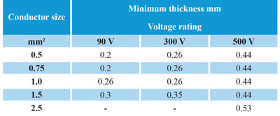
The cables covered by this specification have a maximum nominal voltage of 90 V, 300 V and 500 V a.c.
These cables should not be connected directly to the mains or other low impedance sources.
Multi-element cables for use in analog, digital, and control circuits are not designed for use as power supplies.
1) Conductor
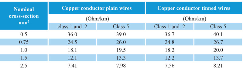
Conductors shall be solid, stranded or flexible clad or plain copper conforming to Class 1, 2 or 5 HD 383 (equivalent to IEC 60228) in the range 0.5 mm2 to 2.5 mm2.
For multi-core cables, the maximum conductor resistance should be the same as HD 383 (equal to IEC 60228), and for multi-pair, multi-triple and multi-quadruple cables, the maximum resistance of HD 383 should be increased by 2%.
Conductor connections must comply with EN 50288-1 (IEC 60228).
Stranded and flexible conductors must consist of wires with a circular cross-section, without insulation between them, with concentric or bundled strands.
When the installed cable length results in high conductor resistance, a larger conductor size can be used.
Values are derived from DIN VDE 0295 (equivalent to the international standard IEC 60228 and HD 383) based on cross section and conductor class, starting with a nominal cross section of 0.5 mm2.
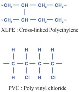
2) Insulation
The insulation material should be selected from the items listed below.
a) PVC EN 50290-2-21
b) Polyethylene EN 50290-2-23
c) Polypropylene EN 50290-2-25
d) Halogen free F.R EN 50290-2-26
e) Cross-linked polyethylene EN 50290-2-29
The minimum thickness at any point of the insulation should not be less than the value given in the table below.
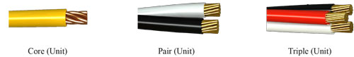
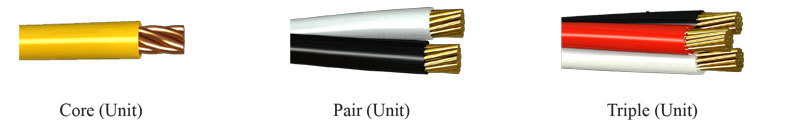
3) cable elements
The cable element consists of:
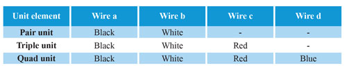
An insulated wire, or a pair consisting of two insulated conductors twisted together and marked wire “a” and wire “b”, or a triple wire consisting of three insulated conductors twisted together and wire “a”, “b” and wire are marked. “c” is determined by the order of turns, or a square consisting of four insulated conductors twisted together and the order of turns of wire “a”, wire “c”, wire “b” and wire “d”.
Wires “a” and “b” form pair 1 and wires “c” and “d” form pair 2.
The length of the bed of a pair, triple or quad should not exceed 100 mm for cables with a conductor cross-section of 1.5 mm2, nor 150 mm for cables with a conductor cross-section of 2.5 mm2.
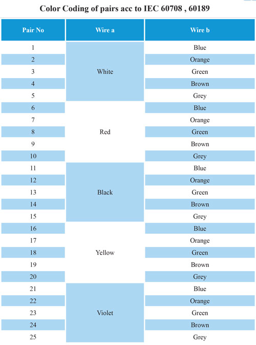
4) Identification of cabling elements
Unless otherwise specified. Using numbered cores or strips, coding for identification shall be in accordance with IEC 60189-2 or EN 60708 (IEC 60708).
5) Screening of cabling elements
Unless otherwise specified. Using numbered cores or strips, coding for identification shall be in accordance with IEC 60189-2 or EN 60708 (IEC 60708).
1-5) Simple or coated metal braid
2-5) A combination of a foil and a plain or coated metal strip.
When using this type of screen, the use of a drain wire is optional.
3-5) A foil with a minimum overlap of 20% and with the discharge wire in direct contact with the metal side of the foil.
If the drain wire is installed, it must be in contact with the main plate element. The discharge wire is either solid or stranded, made of plain or metal-clad copper wire.
Caution should be used when placing dissimilar metals in contact with each other. Covers or other protection methods may be required to prevent galvanic interactions.
6) Screening the cable core
The cable core must be protected by a protective layer when covered with a screen. When the screening of the cable core is specified, it should be selected from those mentioned in the above section. Screening on the cable core may also be in the form of a multilayer sheath.
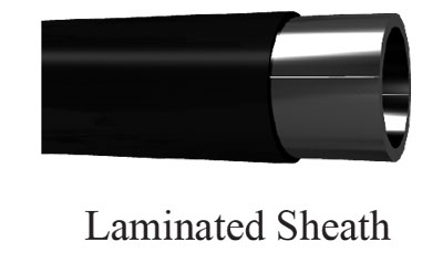
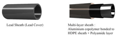
7) Chemical and/or environmental protection
When chemical or environmental protection is required, one of the following methods should be used.
7-1) Lead sheath
2-7) multi-layer sheath (including a multi-layer sheath and an additional layer of polyamide)
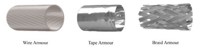
8) Metal protection
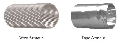
If required by the specifications of the relevant section, the armor must include one or more of the following items:
8-1) layer of round or flat galvanized steel wires;
8-2) single or double layer steel or brass strips;
3-8) Galvanized steel or tinned copper wire braid.
9) Outer cover
The outer covering material must be suitable for the operating environment and may be selected from the materials listed below:
a) PVC EN 50290-2-22
b) Polyethylene EN 50290-2-24
c) Halogen free F.R EN 50290-2-27
10) animal protection (anti-termite and/or anti-rodent)
The relevant section specification should detail the animal protection required to protect the cable against animal attack (such as rodents or termites).
Protection may be a choice of armor, special packing tape, choice of outer sheath material or any combination of these.
Summary of VDE 0816
Outdoor cables for telecommunication and information systems, signaling and measurement cables and mining cables.
Range
This standard applies to outdoor cables for telecommunication and information processing systems, which are divided into “signaling and measurement cables” and “mining cables”.
It does not apply to cables that have special requirements in terms of structure and characteristics due to electrical or mechanical reasons.
Signaling and measurement cables:
The cables are layered and as strand components contain cores with copper conductors with a diameter of 0.9, 1.4 or 1.8 mm. Conductor insulation is made of polyethylene.
1) Conductor
The simple and solid copper conductor is annealed. Usually 0.9, 1.4mm (0.8, 1.8mm also available).
The conductors must be made of soft copper and of completely satisfactory quality, the breaking length of the conductors in the cable must be at least 15%. Existing connections shall not impair the fully satisfactory nature of the conductor. The tensile strength of the connection in a conductor must be at least 90% of the tensile strength of the conductor without the connection.
2) Insulation
Polyethylene insulation must conform to composition 2YI1 according to DIN VDE 0207. d.
3) Cabling element
A cabling element must be an insulated conductor (core) to create a multi-core cable
– A pair of two insulated conductors that are twisted together and wire a and wire b are marked
– The four insulated conductors are twisted together and marked as wire a, wire b, wire c, and wire d.
String components in all layers are counted sequentially in the same direction, starting from the first layer (inner layer). In doing so, start with the primary component in each layer
4) Threading
Cable elements must be converted into a number of sub-units or units that can be serially cut to produce the required number of cores, pairs or quads.
5) Filling
For filled cables (if requested), the cable core gaps must be continuously filled with a suitable compound to prevent water penetration into the cable.
6) Core protection
The cable core may have a protective layer (for example, a spiral or longitudinal covering of one or more strips).
7) shield (protection against electromagnetic fields)
The cable shield is selected to match the required reduction factor requirements. Could be ; Copper strip or copper wire
8) armor (protection against mechanical damage)
If required by the specifications of the relevant section, the armor must include one or more of the following items:
1-8) layer of round galvanized steel wires;
2-8) One or two layers of steel tape
9) Sheath
The inner and outer sheath of the cable is usually PVC.
The PVC sheath must comply with the combination type YM1 in accordance with DIN VDE 0207 part 5.
-Optional: The structure of aluminum multi-layer polyethylene sheath is specified for both underground and aerial cables. This type of sheath also offers screening.
-Optional: A lead sheath can be provided to the cable core for additional shielding and protection against ingress of liquids and chemicals.
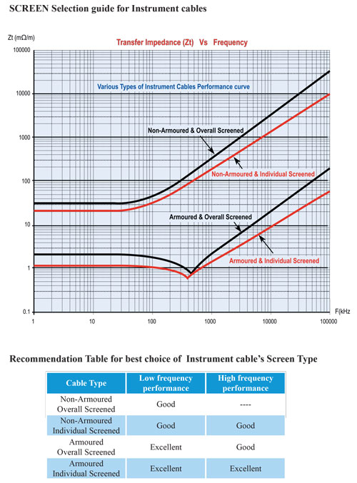
The effectiveness of the shield
Transfer impedance
Transfer impedance is a fundamental performance value of a shield.
Impedance relates the flow of current on one shield surface to the voltage drop caused by this current on the opposite shield surface. This value depends only on the structure of the shield.
Transmission impedance test data is obtained with a terminated triaxial test fixture. This test method, which is a modification of an existing IEC test method, is the same as that proposed by Kenneth Simmons.
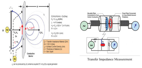
The figure above shows the relationship between the radiation and transmission impedance methods. In the radiating case (A), an EF coupled to the antenna induces current into the RF gasket material. To measure the transmission impedance (B), a signal generator is used. Zst is a complex quantity that combines the material’s DC surface resistance (Rs) and its surface inductive reactance (Xsl).
The transmission impedance is defined as follows: Zt = (1/I0) x (dV/dx)
where I0 is a longitudinal disturbance current created on one surface (either the inner or outer surface) of the shield and dv/dx is the longitudinal voltage per unit length produced by I0 and appearing on the opposite surface of the shield.
In the terminated three-axis test system, the center conductor of the test cable and the shield of an internal end three-axis test system, the center conductor of the test cable and the shield form an internal transmission system, with the shield and the outer concentric tube form an external transmission system. give .
The outer system is driven by a generator and creates a current I0 on the outer surface of the shield. This current creates a voltage difference on the opposite surface in the form of V1 and V2 along the shield X.
This produces signals in the test cable that can be related to the value of the shield transfer impedance.
Result :
The lower the transmission impedance, the more effective the protection.
The transmission impedance value can theoretically be used to determine absolute interference levels.
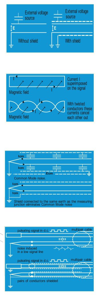
Types of noise and their effect on cables
To connect the converter to the device, the cable sends a very low e.m.f. the mark.
A noise-free signal is important to avoid errors.
Therefore, the cable must be screened against static or magnetic fields that can induce unwanted e.m.f.
There are four different sources of noise as follows:
Magnetic noise
Generally low frequency electromagnetic field due to power cable, motor, ctc. can induce an e.m.f. To instrument cable, the twisted conductors provide a good reduction of magnetic noise. Another reduction is made by steel ducts, armors (high inductance materials). Are some special low resistance screen items (eg copper strips, copper strips) may be necessary.
Common mode noise
This is typical interference that occurs when an instrument loop is grounded on both sides at a different potential. To prevent this noise, the shield, instrument or hot junction of the thermocouple should be normally grounded.
Cross talking voice
This is caused by the unbalanced capacity of adjacent cabling elements with different structures. To reduce this noise for pair/triad/quad cables, different twists are used or, more effectively, each pair/triad/quad is individually shielded (ie 100% aluminum/polyester sheathing) and usually earthed.
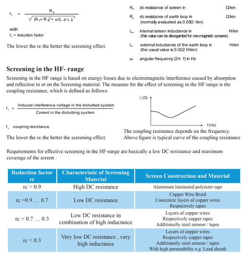
Screen reduction factor
External interference
Screening against external interference must take into account the effect of electrical and magnetic interference and distinguish between LF and HF fields. The required screen design depends on the type and strength of the interference.
Screening in the LF range
For screening in the LF range – that is, in the frequency range up to 10 kHz – the effect of electrical and magnetic interference can be considered separately. If conductive screens are used, the interference of electric fields can be practically ignored. The lower the dc resistance, the better the screening effect. However, care must be taken to ensure a high degree of shielding, as the electric field may otherwise affect the cable core. Screening against LF magnetic interference requires the use of magnetic materials such as steel wires or (even better) tapes. High permeability materials should be used for high screening levels.
A measure of the screening effect in the LF range is the reduction factor. This is the ratio of the interference voltage with the screen to the interference voltage without the screen and is calculated according to the following formula:
Other technical information
Do you need advice?